Data Center HVAC Control System
01.Overview
Data Center HVAC & Environmental Control System
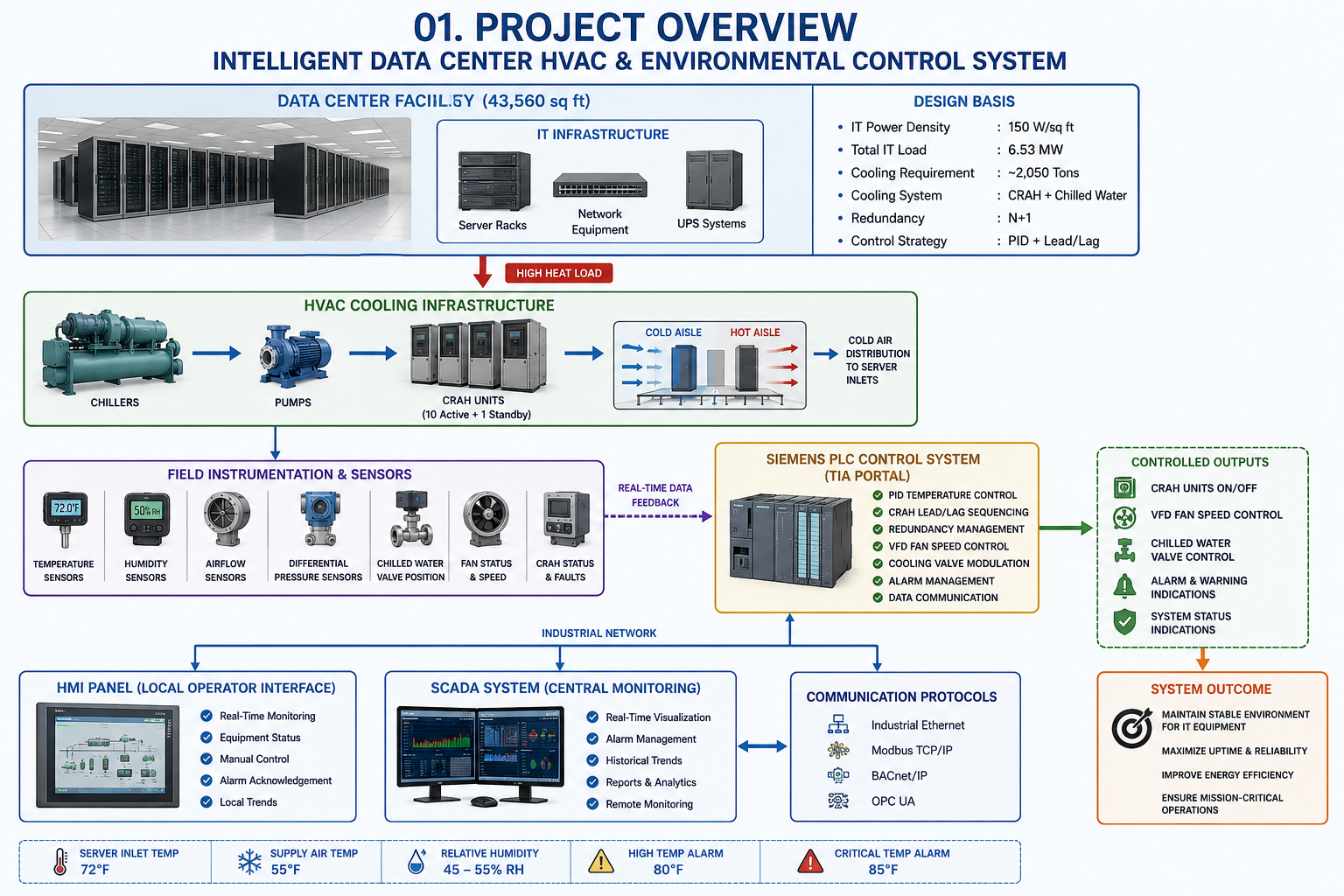
This project designs a mission-critical HVAC automation system for a modern data center using Siemens
TIA Portal, PLC programming, HMI/SCADA systems, PID temperature control, and industrial networking.
The system continuously monitors and controls temperature, humidity, airflow, chilled water cooling, and
CRAH unit operation to maintain stable environmental conditions for critical IT infrastructure.
The project follows modern data center engineering practices based on ASHRAE thermal guidelines,
HVAC cooling standards, energy-efficient airflow management, and real-world mission-critical facility requirements.
02. Facility Design Basis
Data Center Design Parameters
Facility Design Parameters
Facility Size: 43,560 sq ft
IT Power Density: 150 W/sq ft
Total IT Load: 6.53 MW
Cooling System: CRAH + Chilled Water
Cooling Redundancy: N+1
Control Platform: Siemens PLC
Control Strategy: PID + Lead/Lag
Airflow Strategy: Hot Aisle / Cold Aisle
03. Cooling Load Calculation & HVAC Design
Cooling System Design
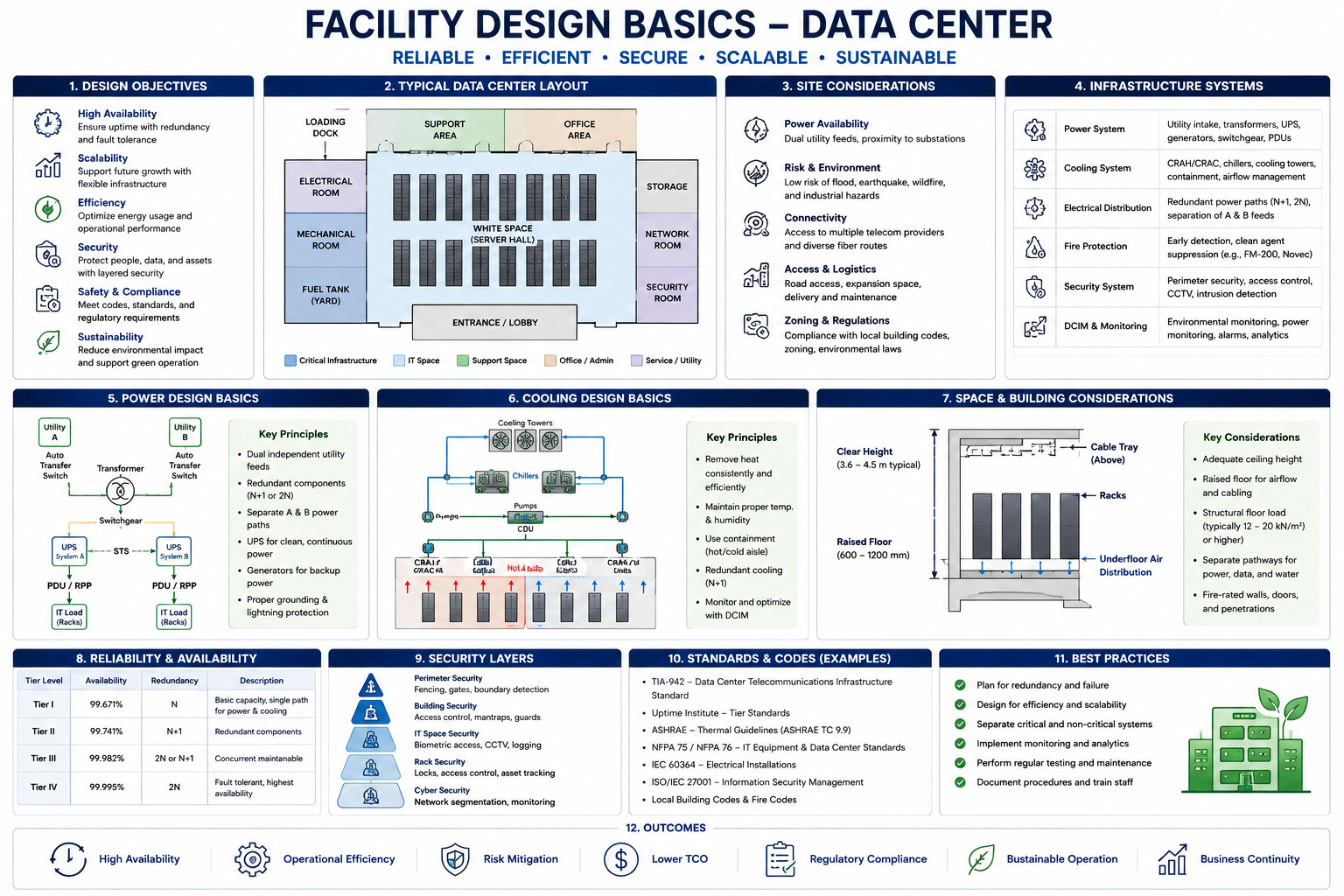
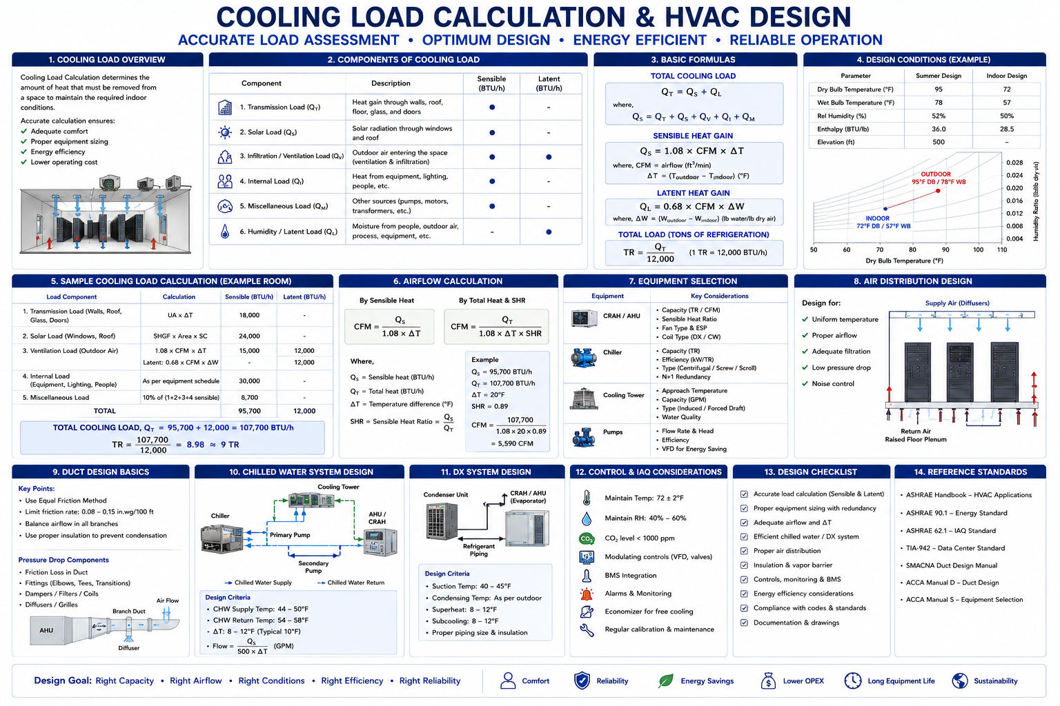
The data center cooling system is designed based on IT power density and heat generation.
Since nearly all electrical power consumed by servers becomes heat, the HVAC system must
continuously remove large thermal loads while maintaining stable operating temperatures.
The total IT load is approximately 6.53 MW, resulting in a cooling requirement of
approximately 2,050 tons after applying design safety margins.
The HVAC system uses chilled water CRAH units with hot aisle/cold aisle airflow
management to improve energy efficiency and maintain proper airflow separation.
IT Load: 43,560 sq ft × 150 W/sq ft = 6,534,000 W
IT Load: 6,534 kW / 6.53 MW
Heat Load: 6,534 kW × 3,412 = 22,295,000 BTU/hr
Cooling Tons: 22,295,000 ÷ 12,000 = 1,858 tons
Design Safety Margin: 10%
Final Cooling Requirement: ≈ 2,050 tons
04. Environmental Targets
Temperature & Humidity Design Parameters
Server Inlet Temperature: 72°F
Supply Air Temperature: 55°F
Relative Humidity: 45–55% RH
High Temperature Alarm: 80°F
Critical Temperature Alarm: 85°F
ASHRAE thermal guidelines emphasize maintaining controlled environmental
conditions to improve equipment reliability and thermal stability.
05. CRAH Cooling Architecture
Precision Cooling System
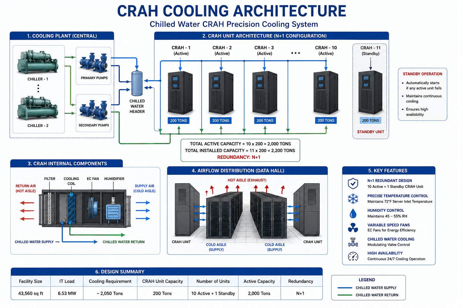
The facility uses multiple CRAH units connected to a chilled water plant. The CRAH units provide precision cooling, humidity control, and high airflow circulation throughout the data center.
The system uses:
10 active CRAH units
1 standby CRAH unit
N+1 redundancy operation
Variable speed fan control
Chilled water cooling valves
The standby CRAH automatically starts if any active unit fails, ensuring continuous cooling operation.
CRAH Unit Sizing
Cooling System Type: Chilled Water CRAH Units
Selected CRAH Capacity: 200 tons per unit
Required Active Units: 10 CRAH units
Standby Units: 1 CRAH unit
Total Installed Units: 11 CRAH units
Total Active Cooling: 10 × 200 = 2,000 tons
Total Installed Cooling: 11 × 200 = 2,200 tons
Redundancy: 10 Active + 1 Standby = N+1
Chilled water systems are commonly used for large data centers because they are more energy efficient at larger scale, although more complex to install and maintain.
06. Airflow Management
Hot Aisle / Cold Aisle Configuration
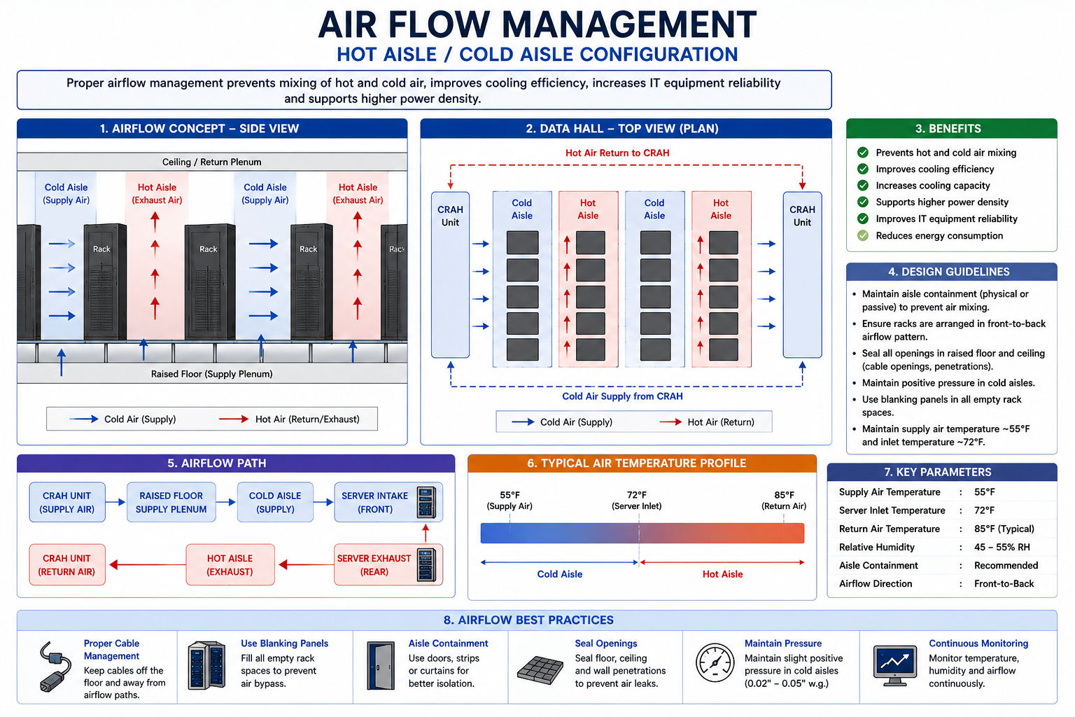
The data center uses hot aisle/cold aisle airflow management to improve cooling efficiency and reduce air mixing.
Cold air is supplied from CRAH units into the cold aisles where server racks intake cooling air.
Hot exhaust air is separated into hot aisles and returned back to the CRAH units for cooling.
This airflow strategy:
Improves cooling efficiency
Reduces energy consumption
Increases cooling capacity
Improves equipment reliability
Precision Cooling Airflow
Precision cooling equipment typically uses higher airflow than comfort cooling systems.
The uploaded HVAC cooling reference states that precision cooling equipment commonly supplies 500–900 CFM per cooling ton.
Selected Airflow Rate: 600 CFM/ton
Active Cooling Capacity: 2,000 tons
Total Airflow Required: 2,000 × 600 = 1,200,000 CFMAirflow per Active CRAH: 1,200,000 ÷ 10 = 120,000 CFM per CRAH
07. Control System Architecture
Siemens PLC-Based HVAC Automation
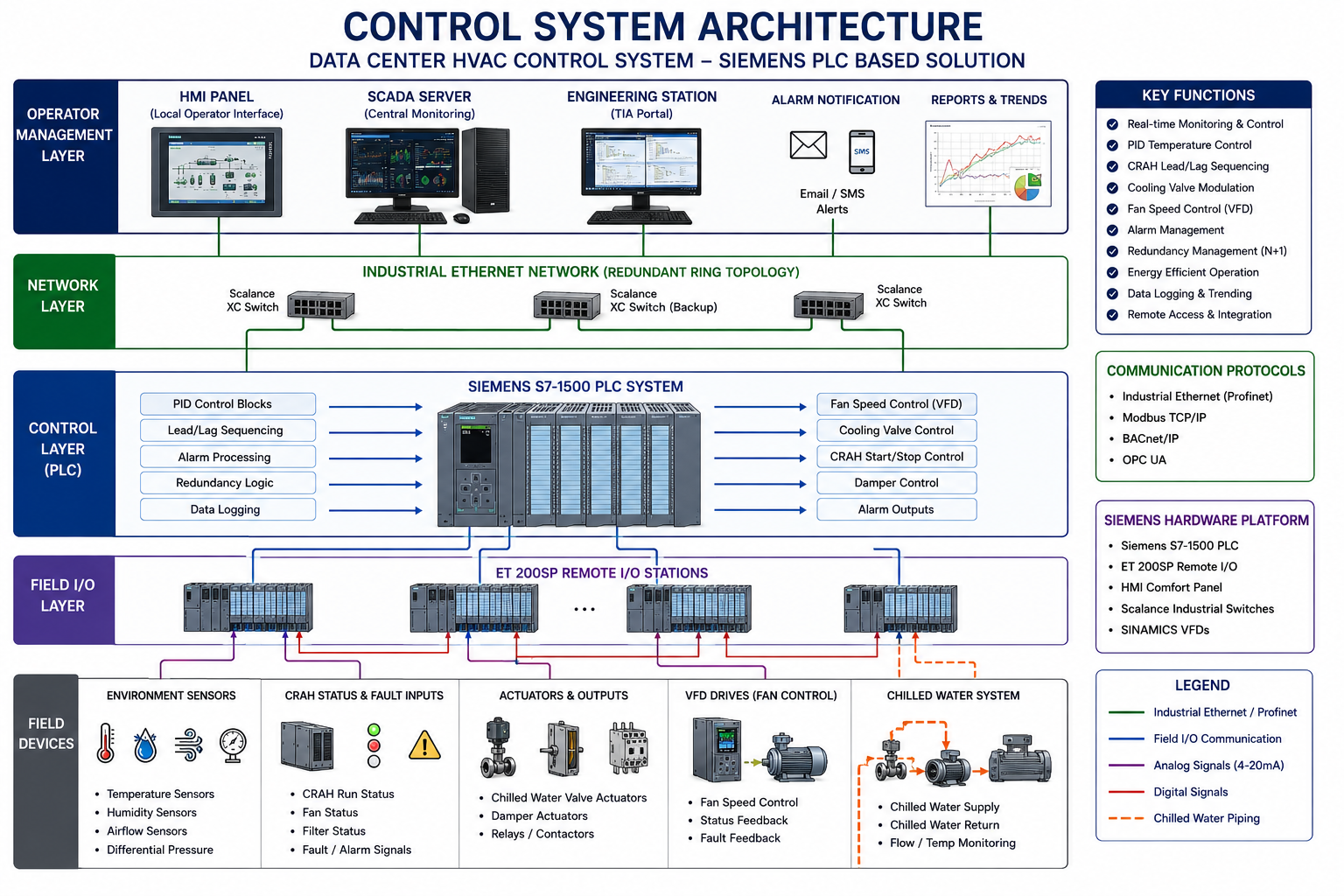
The entire HVAC system is controlled using Siemens PLC automation programmed in TIA Portal.
The PLC continuously:
Reads environmental sensors
Executes PID temperature control
Controls CRAH units
Modulates fan speeds
Adjusts cooling valves
Detects faults
Generates alarms
Communicates with SCADA
The architecture includes:
Field instrumentation
Siemens PLC controller
HMI panel
SCADA server
Industrial Ethernet network
BACnet/IP and Modbus communication
08. Sensor & Instrumentation System
Environmental Monitoring
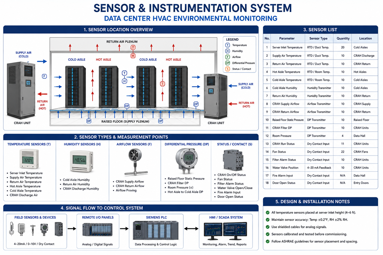
The HVAC automation system continuously monitors:
Room temperature
Supply air temperature
Return air temperature
Relative humidity
Airflow status
Differential pressure
CRAH operating status
The sensors provide real-time feedback to the PLC for precise environmental control and alarm generation.
09. PID Temperature Control
Intelligent Cooling Regulation
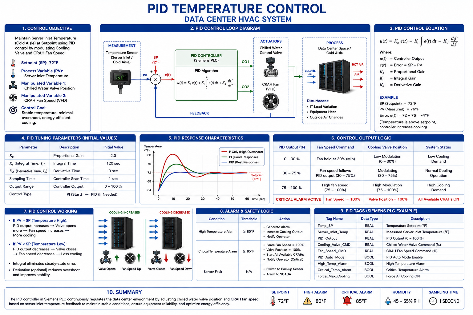
The system uses PID control loops to maintain stable server inlet temperatures.
The PID controller continuously compares:
Temperature setpoint
Actual room temperature
The PLC automatically adjusts:
CRAH fan speed
Cooling valve position
Cooling demand
This provides:
Stable temperature control
Reduced overshoot
Improved energy efficiency
Better airflow regulation
Setpoint: 72°F
Process Variable: Average Server Inlet Temperature
Manipulated Variable 1: Chilled Water Valve Position
Manipulated Variable 2: CRAH Fan Speed Command
Output Range: 0–100%
Normal Fan Minimum: 30%
High Load Fan Command: 75%
Critical Cooling Command: 100%PID Control Equation
Temperature Error
Error = Setpoint − Process Variable
Example:
Setpoint: 72°F
Measured Server Inlet Temperature: 76°F
Error: 72 − 76 = −4°FSince the measured temperature is above setpoint, the PLC increases cooling output.
PID Initial Tuning Values
Starting Values for Simulation
Proportional Gain Kp: 2.0
Integral Time Ti: 120 seconds
Derivative Time Td: 0 seconds
Control Type: PI control first, PID later if needed
Sampling Time: 1 second
Output Lower Limit: 0%
Output Upper Limit: 100%Use PI control first because HVAC temperature response is slow and derivative action can make the loop noisy.
PID Control Action
Cooling Response
If Server Inlet Temperature rises above 72°F, the PLC increases cooling valve position and fan speed.
If Server Inlet Temperature drops below 72°F, the PLC reduces cooling output.
If temperature reaches 80°F, the system generates a high temperature alarm.
If temperature reaches 85°F, the system forces maximum cooling and starts all available CRAH units.PID Output Mapping
Control Output Logic
PID Output 0–30%: Fan held at 30%, valve modulates low cooling
PID Output 30–75%: Fan speed follows PID output
PID Output 75–100%: High cooling demand
Critical Alarm Active: Fan speed 100%, valve 100%, all available CRAHs ON
10. CRAH Lead/Lag Operation
Redundant Cooling Logic
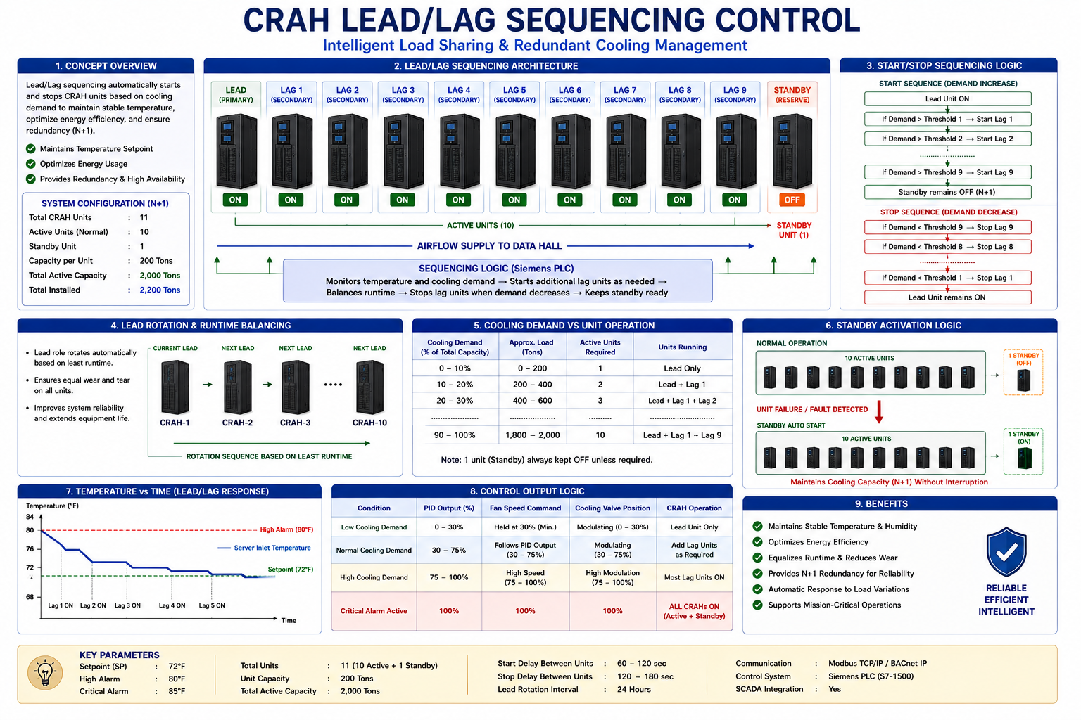
The HVAC system uses lead/lag control logic to balance CRAH runtime and improve equipment reliability.
The PLC automatically:
Starts lead CRAH units
Rotates runtime hours
Starts lag units during high load
Starts standby units during failures
Redistributes cooling load
This redundancy strategy ensures continuous operation under fault conditions.
11. Alarm Management System
Critical Alarm Handling
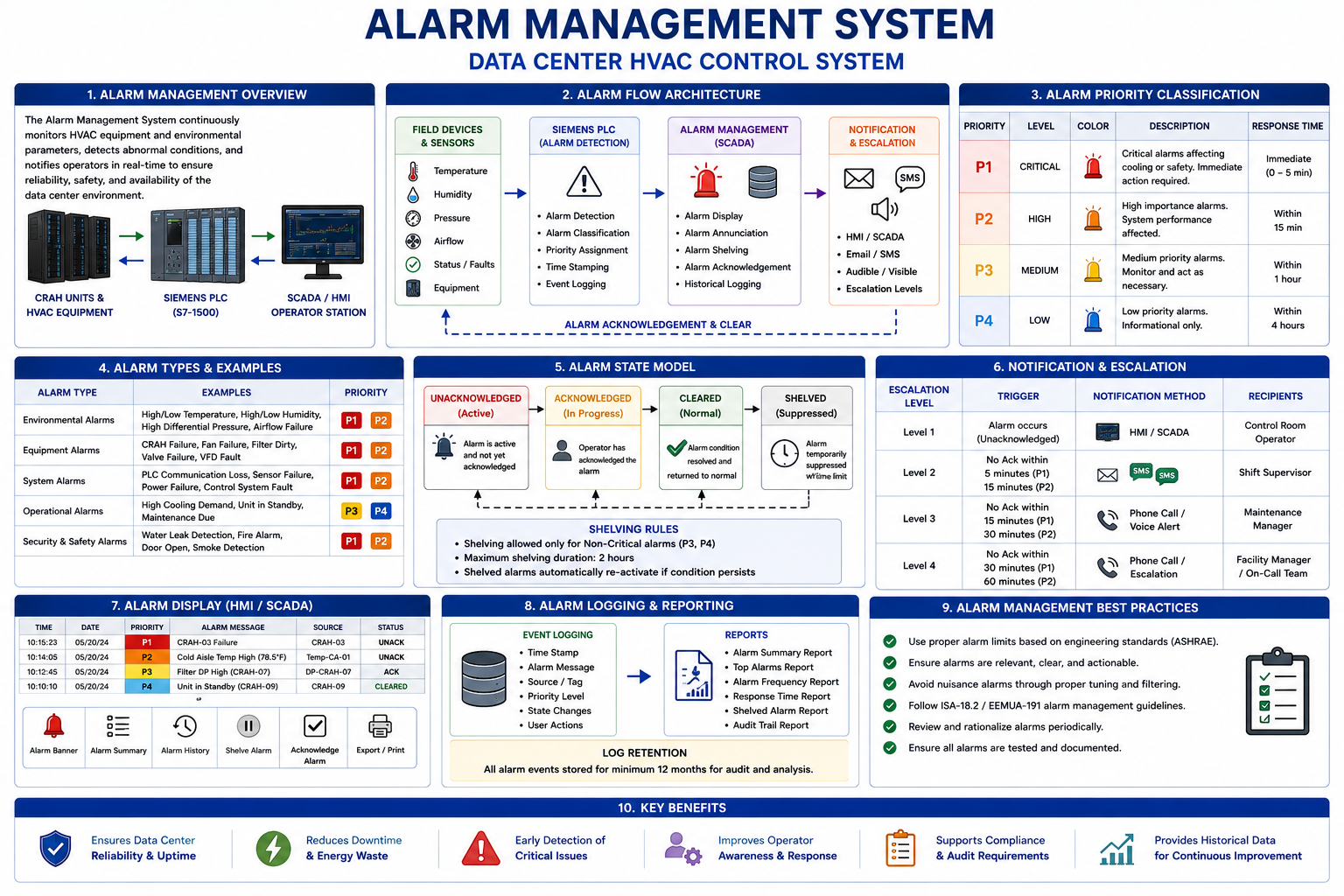
The PLC continuously monitors system conditions and generates alarms for abnormal operating conditions.
Main alarms include:
High temperature
Critical temperature
CRAH fault
Low airflow
High humidity
Sensor failure
Fire alarm
Emergency stop
The SCADA system displays alarm priorities, alarm history, and operator notifications.
12. Siemens PLC Programming
Ladder Logic & Automation
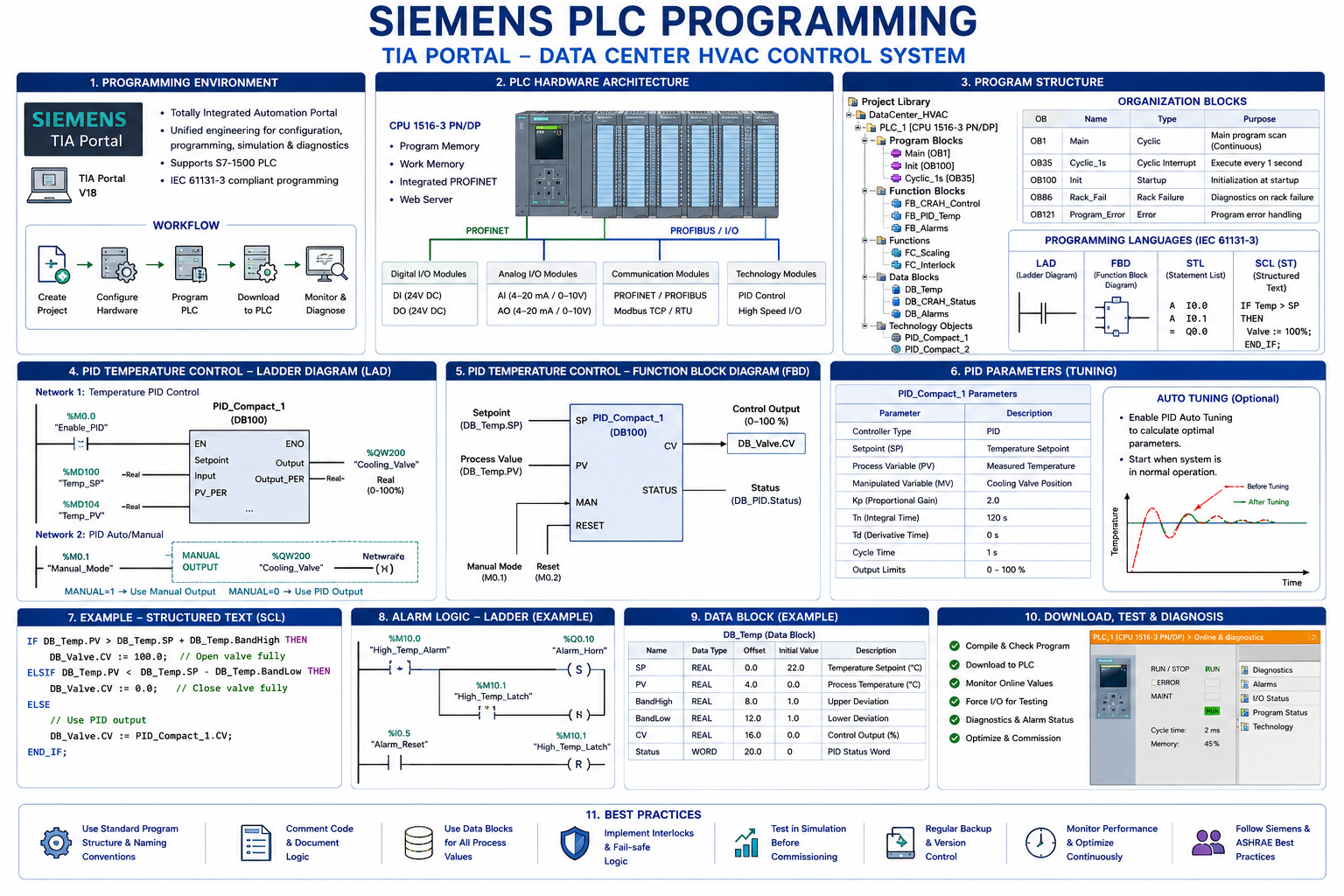
The HVAC control logic is programmed using Siemens ladder logic inside TIA Portal.
The PLC program includes:
System permissive logic
Auto/manual operation
CRAH start/stop logic
PID control blocks
Alarm handling
Failover sequences
Fan speed control
Cooling valve modulation
The PLC continuously scans system inputs and updates outputs in real time.
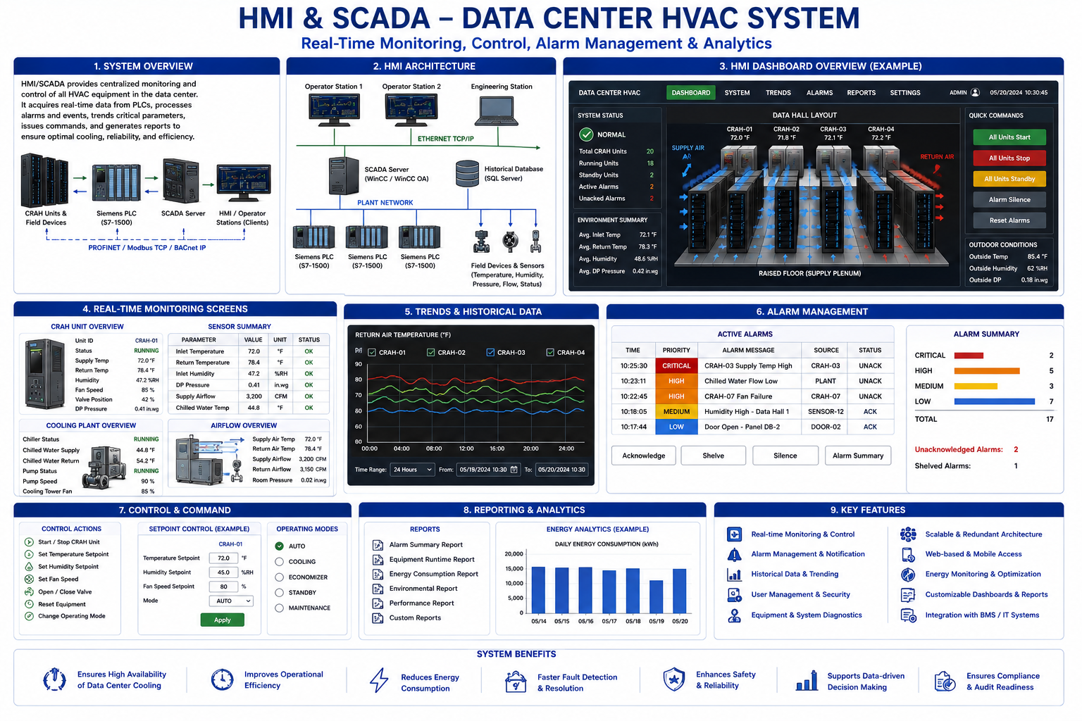
13. HMI & SCADA System
Real-Time Monitoring & Visualization
The HMI and SCADA system provide operators with real-time monitoring and control of the HVAC system.
Main HMI features include:
Overview dashboard
CRAH status screens
Alarm dashboard
Trend graphs
Temperature monitoring
Fan speed monitoring
Manual override controls
The SCADA system also stores historical trends and alarm logs for analysis.
14. Industrial Networking
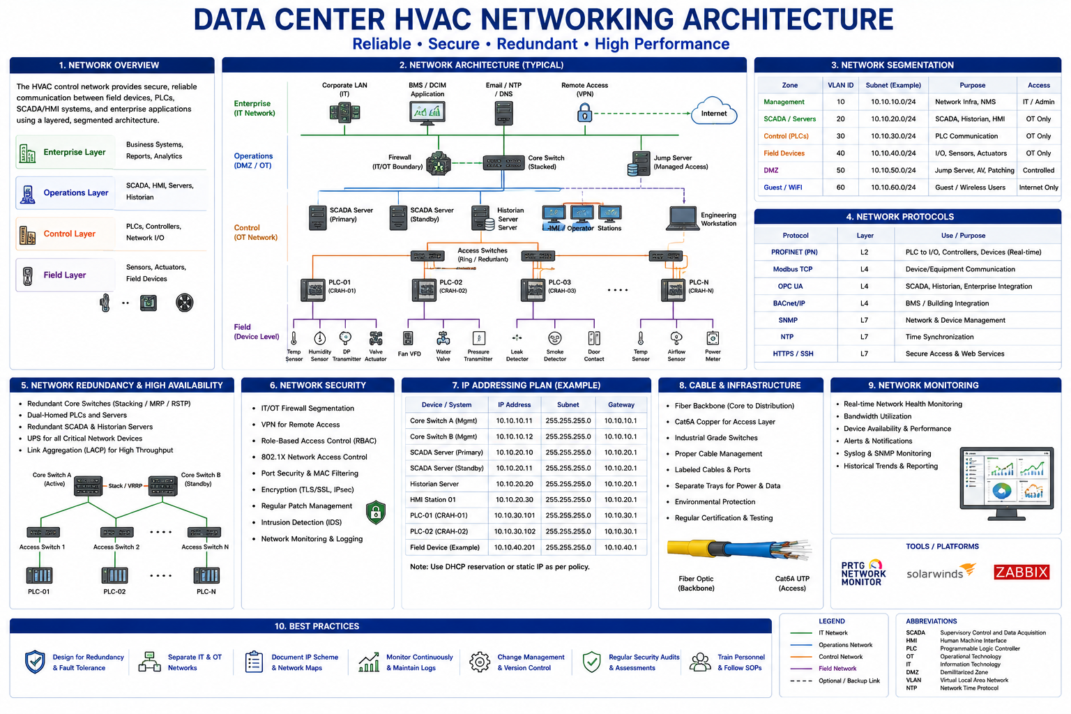
Communication Architecture
The automation system uses industrial networking for communication between PLCs,
HMI panels, SCADA servers, and HVAC equipment.
Protocols include:
Industrial Ethernet
Modbus TCP/IP
BACnet/IP
OPC UA
The network architecture allows centralized monitoring and integration with building management systems.
15. Energy Efficiency Strategy
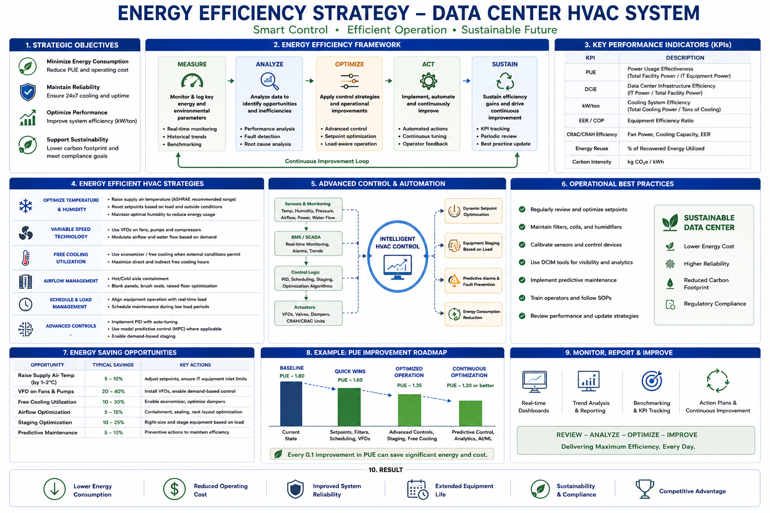
Optimized Cooling Operation
The HVAC design follows energy-efficient data center cooling principles including:
Hot aisle/cold aisle airflow separation
Variable frequency drives
PID cooling optimization
Chilled water cooling
Runtime balancing
Efficient airflow management
These strategies improve cooling performance while reducing energy consumption.
16. Final Project Outcome
Mission-Critical HVAC Automation System
The completed project demonstrates a realistic industrial-grade data center HVAC automation system using Siemens PLC programming, HVAC controls engineering, SCADA development, PID temperature control, industrial networking, and mission-critical cooling redundancy.
The project showcases:
Siemens TIA Portal programming
PLC ladder logic
HVAC automation
CRAH precision cooling
SCADA monitoring
Alarm management
Redundant cooling operation
Industrial control system design
This project is designed as a professional engineering portfolio project suitable for automation, controls, HVAC, BAS/BMS, and mission-critical data center engineering roles.